
Saturday, April 9, 2016

Friday, April 8, 2016
STAR AND DELTA CONNECTION BASICS.
Comparison between Star and Delta Connections
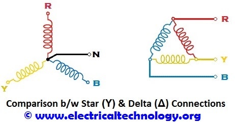 Comparison between Star (Y) and Delta (Δ) Connections
|
Star (Y) Connection
|
Delta (Δ) Connection
|
| In
STAR connection, the starting or finishing ends (Similar ends) of three
coils are connected together to form the neutral point. A common wire
is taken out from the neutral point which is called Neutral. | In
DELTA connection, the opposite ends of three coils are connected
together. In other words, the end of each coil is connected with the
start of another coil, and three wires are taken out from the coil
joints |
| There is a Neutral or Star Point | No Neutral Point in Delta Connection |
| Three phase four wire system is derived from Star Connections (3-Phase, 4 Wires System) We may Also derived 3 Phase 3 Wire System from Star Connection | Three phase three wire system is derived from Delta Connections (3-Phase, 3 Wires System) |
| Line Current is Equal to Phase Current. i.e. Line Current = Phase Current
IL = IPH
| Line Voltage is Equal to Phase Voltage. i.e. Line Voltage = Phase Voltage
VL = VPH
|
| Line Voltage is √3 times of Phase Voltage. i.e.
VL = √3 VPH
| Line Current is √3 times of Phase Current. i.e.
IL = √3 IPH
|
| The Total Power of three phases could be found by
P = √3 x VL x IL x CosФ …. Or
P = 3 x VPH x IPH x CosФ
| The Total Power of three phases could be found by
P = √3 x VL x IL x CosФ … or
P = 3 x VPH x IPH x CosФ
|
| The speeds of Star connected motors are slow as they receive 1/√3 voltage. | The speeds of Delta connected motors are high because each phase gets the total of line voltage |
| In
Star Connection, the phase voltage is low as 1/√3 of the line voltage,
so, it needs low number of turns, hence, saving in copper. | In Delta connection, The phase voltage is equal to the line voltage, hence, it needs more number of turns. |
| Low insulation required as phase voltage is low | Heavy insulation required as Phase voltage = Line Voltage. |
| In Power Transmission, Star Connection system is general and typical to be used. A COMMON EXAMPLE HOW THREE PHASE MOTOR TERMINAL ARE CONNECTED IN STAR AND DELTA FORMATION. | In Power Distribution and industries, Delta Connection is general and typical to be used. |
Wednesday, April 6, 2016

Monday, April 4, 2016
LEADING AND LAGGING IN ELECTRICAL ENGINEERING.
There are three options in a circuit for current. It can be leading, lagging,
or in phase with voltage. These can all be seen when one maps current
and voltage of alternating (AC) circuits against time. The only time
that the voltage and current are in phase together is when the load is
resistive. If at some point in the phase shift the current leads the
voltage by more than 90 degrees, it can then be stated that the current
lags that voltage by 180 degrees minus the phase shift. Ninety degrees
phase shift is the determining point if the current is either leading or
lagging the voltage.[1]


what is pahse difference in electrical engineering.?
PHASE DIFFERENCE:
in general language the phase difference or phase shift can be determined as the change in angle of current and voltage waveform in particular time T.
LET S ILLUSTRATE THIS WITH A EXAMPLE :
graphically in the time domain along an horizontal zero axis, and that sine waves have a positive maximum value at time π/2, a negative maximum value at time 3π/2, with zero values occurring along the baseline at 0, π and 2π. However, not all sinusoidal waveforms will pass exactly through the zero axis point at the same time, but may be “shifted” to the right or to the left of 0o by some value when compared to another sine wave.
For example, comparing a voltage waveform to that of a current waveform. This then produces an angular shift or Phase Difference between the two sinusoidal waveforms. Any sine wave that does not pass through zero at t = 0 has a phase shift.
The phase difference or phase shift as it is also called of a Sinusoidal Waveform is the angle Φ (Greek letter Phi), in degrees or radians that the waveform has shifted from a certain reference point along the horizontal zero axis. In other words phase shift is the lateral difference between two or more waveforms along a common axis and sinusoidal waveforms of the same frequency can have a phase difference.
The phase difference, Φ of an alternating waveform can vary from between 0 to its maximum time period, T of the waveform during one complete cycle and this can be anywhere along the horizontal axis between, Φ = 0 to 2π (radians) or Φ = 0 to 360o depending upon the angular units used.
Phase difference can also be expressed as a time shift of τ in seconds representing a fraction of the time period, T for example, +10mS or – 50uS but generally it is more common to express phase difference as an angular measurement. Then the equation for the instantaneous value of a sinusoidal voltage or current waveform we developed in the previous Sinusoidal Waveform will need to be modified to take account of the phase angle of the waveform and this new general expression becomes.

Likewise, if the positive slope of the sinusoidal waveform passes through the horizontal x-axis some time “after” t = 0 then the waveform has shifted to the right so Φ <0, and the phase angle will be negative in nature -Φ producing a lagging phase angle as it appears later in time than 0o producing a clockwise rotation of the vector. Both cases are shown below.
 Firstly, lets consider that two
alternating quantities such as a voltage, v and a current, i have the same frequency ƒ in Hertz. As the
frequency of the two quantities is the same the angular velocity, ω must also be the same. So at any instant in time we can say that the phase of voltage, v will be the same as the phase of the current, i.
Then the angle of rotation within a particular time period will always be the same and the phase difference between the two quantities of v and i will therefore be zero and Φ = 0. As the frequency of the voltage, v and the current, i are the same they must both reach their maximum positive, negative and zero values during one complete cycle at the same time (although their amplitudes may be different). Then the two alternating quantities, v and i are said to be “in-phase”.
 Now lets consider that the voltage, v and the current, i have a phase difference between themselves of 30o, so (Φ = 30o or π/6
radians). As both alternating quantities rotate at the same speed, i.e.
they have the same frequency, this phase difference will remain
constant for all instants in time, then the phase difference of 30o between the two quantities is represented by phi, Φ as shown below.
 The voltage waveform above starts at zero along the horizontal
reference axis, but at that same instant of time the current waveform is
still negative in value and does not cross this reference axis until 30o later. Then there exists a Phase difference
between the two waveforms as the current cross the horizontal reference
axis reaching its maximum peak and zero values after the voltage
waveform.
As the two waveforms are no longer “in-phase”, they must therefore be “out-of-phase” by an amount determined by phi, Φ and in our example this is 30o. So we can say that the two waveforms are now 30o out-of phase. The current waveform can also be said to be “lagging” behind the voltage waveform by the phase angle, Φ. Then in our example above the two waveforms have a Lagging Phase Difference so the expression for both the voltage and current above will be given as.


The phase angle of a sine wave can be used to describe the
relationship of one sine wave to another by using the terms “Leading”
and “Lagging” to indicate the relationship between two sinusoidal
waveforms of the same frequency, plotted onto the same reference axis.
In our example above the two waveforms are out-of-phase by 30o so we can say that i lags v or v leads i by 30o.
The relationship between the two waveforms and the resulting phase angle can be measured anywhere along the horizontal zero axis through which each waveform passes with the “same slope” direction either positive or negative.
In AC power circuits this ability to describe the relationship between a voltage and a current sine wave within the same circuit is very important and forms the bases of AC circuit analysis.
 The Cosine Wave, simply called “cos”, is as
important as the sine wave in electrical engineering. The cosine wave
has the same shape as its sine wave counterpart that is it is a
sinusoidal function, but is shifted by +90o or one full quarter of a period ahead of it.
 Alternatively, we can also say that a sine wave is a cosine wave that has been shifted in the other direction by -90o. Either way when dealing with sine waves or cosine waves with an angle the following rules will always apply.
 When comparing two sinusoidal waveforms it more common to express
their relationship as either a sine or cosine with positive going
amplitudes and this is achieved using the following mathematical
identities.
 By using these relationships above we can convert any sinusoidal
waveform with or without an angular or phase difference from either a
sine wave into a cosine wave or vice versa.
In the next tutorial about Phasors we will use a graphical method of representing or comparing the phase difference between two sinusoids by looking at the phasor representation of a single phase AC quantity along with some phasor algebra relating to the mathematical addition of two or more phasors.
IN THE END WE CONCULUDE THAT THE CHANGE IN THE VALUE OF ANGLE IN THE WAVEFORM OF CURRENT AND VOLTAGE IN A PARTICULAR TIME LEADS TO PHASE SHIFT OR PHASE DIFFERENCEWHERE
in general language the phase difference or phase shift can be determined as the change in angle of current and voltage waveform in particular time T.
LET S ILLUSTRATE THIS WITH A EXAMPLE :
graphically in the time domain along an horizontal zero axis, and that sine waves have a positive maximum value at time π/2, a negative maximum value at time 3π/2, with zero values occurring along the baseline at 0, π and 2π. However, not all sinusoidal waveforms will pass exactly through the zero axis point at the same time, but may be “shifted” to the right or to the left of 0o by some value when compared to another sine wave.
For example, comparing a voltage waveform to that of a current waveform. This then produces an angular shift or Phase Difference between the two sinusoidal waveforms. Any sine wave that does not pass through zero at t = 0 has a phase shift.
The phase difference or phase shift as it is also called of a Sinusoidal Waveform is the angle Φ (Greek letter Phi), in degrees or radians that the waveform has shifted from a certain reference point along the horizontal zero axis. In other words phase shift is the lateral difference between two or more waveforms along a common axis and sinusoidal waveforms of the same frequency can have a phase difference.
The phase difference, Φ of an alternating waveform can vary from between 0 to its maximum time period, T of the waveform during one complete cycle and this can be anywhere along the horizontal axis between, Φ = 0 to 2π (radians) or Φ = 0 to 360o depending upon the angular units used.
Phase difference can also be expressed as a time shift of τ in seconds representing a fraction of the time period, T for example, +10mS or – 50uS but generally it is more common to express phase difference as an angular measurement. Then the equation for the instantaneous value of a sinusoidal voltage or current waveform we developed in the previous Sinusoidal Waveform will need to be modified to take account of the phase angle of the waveform and this new general expression becomes.
Phase Difference Equation
- Where:
- Am - is the amplitude of the waveform.
- ωt - is the angular frequency of the waveform in radian/sec.
- Φ (phi) - is the phase angle in degrees or radians that the waveform has shifted either left or right from the reference point.
Likewise, if the positive slope of the sinusoidal waveform passes through the horizontal x-axis some time “after” t = 0 then the waveform has shifted to the right so Φ <0, and the phase angle will be negative in nature -Φ producing a lagging phase angle as it appears later in time than 0o producing a clockwise rotation of the vector. Both cases are shown below.
Phase Relationship of a Sinusoidal Waveform

alternating quantities such as a voltage, v and a current, i have the same frequency ƒ in Hertz. As the
frequency of the two quantities is the same the angular velocity, ω must also be the same. So at any instant in time we can say that the phase of voltage, v will be the same as the phase of the current, i.
Then the angle of rotation within a particular time period will always be the same and the phase difference between the two quantities of v and i will therefore be zero and Φ = 0. As the frequency of the voltage, v and the current, i are the same they must both reach their maximum positive, negative and zero values during one complete cycle at the same time (although their amplitudes may be different). Then the two alternating quantities, v and i are said to be “in-phase”.
Two Sinusoidal Waveforms – “in-phase”
Phase Difference of a Sinusoidal Waveform
As the two waveforms are no longer “in-phase”, they must therefore be “out-of-phase” by an amount determined by phi, Φ and in our example this is 30o. So we can say that the two waveforms are now 30o out-of phase. The current waveform can also be said to be “lagging” behind the voltage waveform by the phase angle, Φ. Then in our example above the two waveforms have a Lagging Phase Difference so the expression for both the voltage and current above will be given as.
where, i lags v by angle Φ
Likewise, if the current, i has a positive value and crosses the reference axis reaching its maximum peak and zero values at some time before the voltage, v then the current waveform will be “leading” the voltage by some phase angle. Then the two waveforms are said to have a Leading Phase Difference and the expression for both the voltage and the current will be.
where, i leads v by angle Φ
The relationship between the two waveforms and the resulting phase angle can be measured anywhere along the horizontal zero axis through which each waveform passes with the “same slope” direction either positive or negative.
In AC power circuits this ability to describe the relationship between a voltage and a current sine wave within the same circuit is very important and forms the bases of AC circuit analysis.
The Cosine Waveform
So we now know that if a waveform is “shifted” to the right or left of 0o when compared to another sine wave the expression for this waveform becomes Am sin(ωt ± Φ). But if the waveform crosses the horizontal zero axis with a positive going slope 90o or π/2 radians before the reference waveform, the waveform is called a Cosine Waveform and the expression becomes.Cosine Expression
Phase Difference between a Sine wave and a Cosine wave
Sine and Cosine Wave Relationships
In the next tutorial about Phasors we will use a graphical method of representing or comparing the phase difference between two sinusoids by looking at the phasor representation of a single phase AC quantity along with some phasor algebra relating to the mathematical addition of two or more phasors.
IN THE END WE CONCULUDE THAT THE CHANGE IN THE VALUE OF ANGLE IN THE WAVEFORM OF CURRENT AND VOLTAGE IN A PARTICULAR TIME LEADS TO PHASE SHIFT OR PHASE DIFFERENCEWHERE
- here:
- Am - is the amplitude of the waveform.
- ωt - is the angular frequency of the waveform in radian/sec.
- Φ (phi) - is the phase angle in degrees or radians that the waveform has shifted either left or right from the reference point.
Subscribe to:
Posts (Atom)